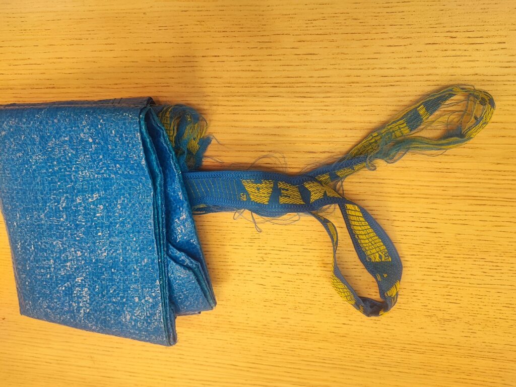
There are a myth or rumor circulating verbally and the internet that Ikea provide 1 to 1 exchanged for damaged Ikea shopping blue bag or known as Frakta. Coincidentally, I have an opportunity to put this myth or rumor to test.
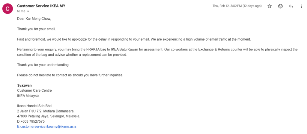
An email was first sent to Customer Service IKEA MY. The reply is promising, as long as I can bring the damage the Frakta to Ikea, the support and return staff shall make accessment to determine extend of the damage to evaluate if 1 to 1 exchange is possible.
This is a summary dieting and body recompositing plan using DeepSeek after 3 months of notes and driven by data.
How to Lose Fat, Build Muscle, and Redefine Your Health After 40
This guide is based on the proven principles demonstrated over a 3-month journey that resulted in:
Weight loss from ~70kg to ~66.6kg.
A drop in resting heart rate into the elite range (~50-60s BPM).
Visible muscle gain and fat loss, confirmed by strength increases and clothing fit.
The reversal of pre-diabetic markers (like a dark neck ring).
Part 1: The Core Formula (The Non-Negotiables)
1. Cardio First, Strength Second: The 1-2 Punch
Cardio (30-45 mins minimum): This is your fat-burning engine. Use incline training (e.g., treadmill at 10-22% incline) for maximum efficiency. It’s not about speed; it’s about sustained effort.
Strength Training (Immediately After): This is your muscle-preserving signal. Do NOT skip this. Muscle is what gives you a defined shape and burns calories at rest.
2. The Gradual Carb Reduction Strategy
Do not shock your system by cutting carbs drastically on day one.
Weeks 1-2: Reduce your typical rice (or other primary carb) portion by 25%. This is a small, manageable change that begins the adaptation process.
This is the greatest hurdle to recondition your mind to resist hunger, if you have history of gastric kindly consult with your doctor or dietician.
After 1 Month: Reduce your original rice portion by 50%. By this point, your stomach and appetite have adjusted, making this new portion feel normal and satisfying, especially when you fill the rest of your plate with protein and vegetables.
This gradual approach builds sustainable habits and avoids the feeling of deprivation that causes most diets to fail.
3. Embrace Intelligent Hunger
The first 2-4 weeks are the hardest. Your body will scream for its old fuel. Fight the urge. This phase shrinks your stomach and retrains your metabolism to burn fat.
This doesn’t mean starving. It means managing hunger with strategic, high-volume, low-calorie foods (vegetables, lean protein).
4. Respect Rest Days
Muscles grow when you rest, not when you train. Rest days are not “lazy” days; they are when the magic happens.
Overtraining will halt your progress and spike your stress hormones.
Part 2: The Execution (How to Do It Right)
The Workout Structure:
Frequency: 4-6 days per week. (2 sets of work out on Monday, Wednesday and Friday)
Sample Day:
Treadmill: 45-60 mins. Use a “progressive and autoregulated” approach: start at a manageable pace/incline and gradually increase. If you feel lightheaded or your legs fatigue, reduce the load immediately. Listen to your body.
Strength Circuit (Post-Cardio): 15-20 mins.
Push: Push-Ups (3 sets of 8-12 reps)
Pull: Dumbbell Rows (e.g., 7.5kg, 3 sets of 8 reps)
Legs/Core: Goblet Squats or Gym Machine (3 sets of 5-8 reps)
Progressive Overload: This is the key to growth. Each week, try to do just a little more—one more rep, one more set, or a slightly heavier weight.
The Nutrition Strategy:
Protein is Priority: Eat 1.6-2.2 grams of protein per kg of body weight. This protects your muscle while you lose fat.
Smart Carbohydrates: Don’t fear carbs; time them. Use the gradual reduction strategy above. Prioritize complex carbs (oats, sweet potato, lentils) to fuel your workouts.
The Phased Plate Method: Start by reducing your carb portion by 25%. After a month, reduce it by 50% from your original amount. Always fill the rest of your plate with protein and vegetables.
Part 3: Tracking & Mindset (The Secret Weapons)
Track Beyond the Scale:
The Mirror & Your Clothes: Are your pants looser in the waist? Are your shirts tighter in the chest/arms? This is the true test.
Performance Metrics: Is the treadmill incline getting easier? Are you lifting heavier weights? This proves you’re building muscle.
Health Markers: Is your resting heart rate dropping? Do you have more stable energy throughout the day? These are signs of improving internal health.
Adopt the Right Mindset:
Focus on Feeling, Not Just Form: The goal is to feel the muscle underneath—the firm biceps, the hard calves, the defined upper abs. The visual “six-pack” is a later byproduct of this.
Consistency Over Perfection: You will have off days. You might eat a large meal. What matters is getting back to the formula immediately after.
It’s a Marathon, Not a Sprint: The last bit of fat (especially the lower belly) is the most stubborn. Be patient and trust the process. The gradual carb reduction is your tool for winning this marathon.
Final Word of Caution and Encouragement
This formula requires discipline. It is demanding. However, the rewards are not just a better-looking body, but a fundamentally healthier one: better sleep, no more energy crashes, reduced disease risk, and the vitality of someone years younger.
Your journey is living proof that through consistent, intelligent effort—including the patient, phased approach to nutrition—you can fundamentally reshape your body and health, no matter your starting point.
Like all AI project, data collection is needed. Treating health improvement program as a sports science requires basic information such as heart rate, and training regime logs.
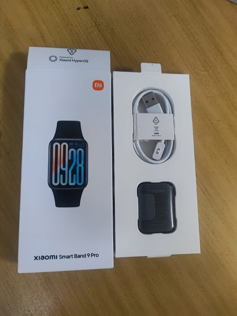
I have started knowing nothing of the metrics other than using intuitively data gathered from smart devices such as the Xiaomi Smart Band 9 Pro which I had bought in late June 2025.
It is a commitment to start a healthy lifestyle; as a sunken cost fallacy to start working out using data driven motivation for self-improvement.
A device to get data of your health, Xiaomi Smart Band 9 Pro
It has a for android, the Mi Fitness which will provide telemetry needed.
Most of the bursary apps in Malaysia does not have the mechanism to perform full subscription to right issue on your counter.
The most the app could do is to sell or start the right issue from the app.
Instead of selling the right issue from the app as an immediate profit. To buy the subscription, the person of interest needs to “bid” to buy the numbers of right issue from the app. After bidding the right issue, it does not means you have subscribed fully. You have just buy the right to subscribe to the right issue.
Luckily my remiser has helped me through the process.
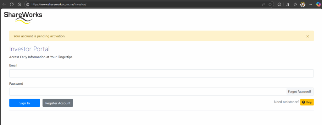
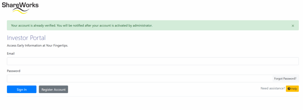
Once, upon subscription go to other 3rd party such as Shareworks to create your account. Do follow up with the staffs for the activation of the account once expedited by your remiser it may take a single working day. Make sure you have your CDS account number. Get it from your remiser or from your bursary statement.
After an account is created this is the expected response from the websiteUpon activation, wait for the account to be verified
Once the account is done, time to login to the Shareworks website and proceed to perform subscription to right issue. If everything is good you should see the right issue on the Sharework in your account.
Right issue in your account
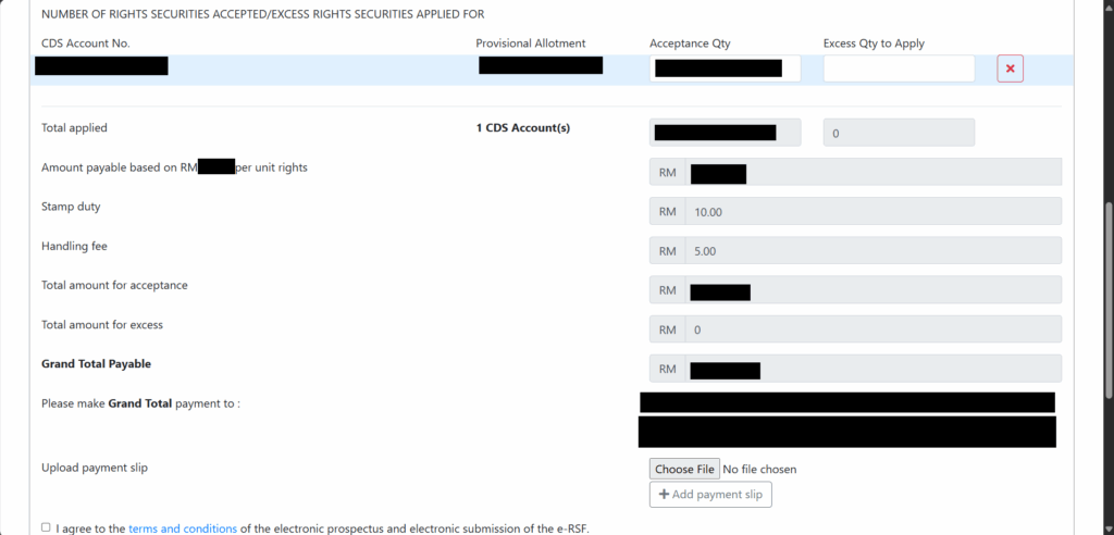
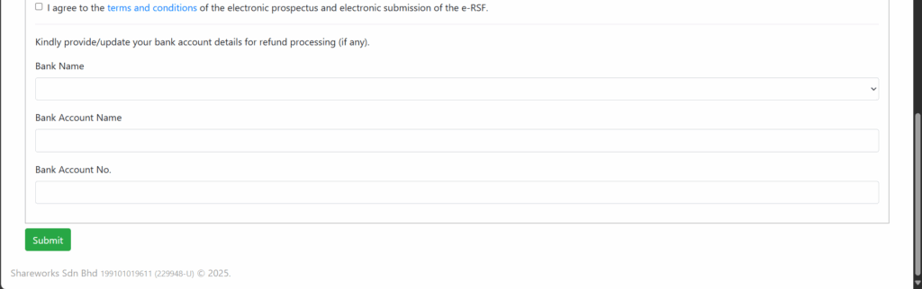
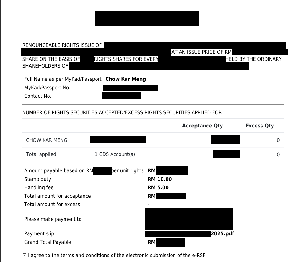
Fill up the e-form.
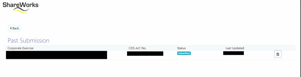
This part of the e-form are autofilledFill up the numbers of shares of right issue, make payment based on the instructions given on the right column “Please make Grand Tota payment in”Fill up your banking account incase refund of your purchase should your subscription is unsuccessfulUpon submitting your subscription, status will show submittedDownload and verify submitted e-form
Follow up with the contact in sharework a few working day later to check the status.
Subscribe into right issue is a good learning experience. However, the discounted price right issue however is not too far off from the lower price of the ordinary share in the share market. It is due to my lack of experience in the share market works. A large bulk of the discount is offset by the bidding to earn right to subscription of right issue.
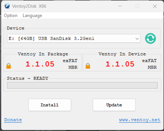
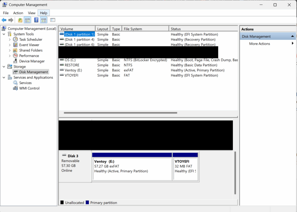
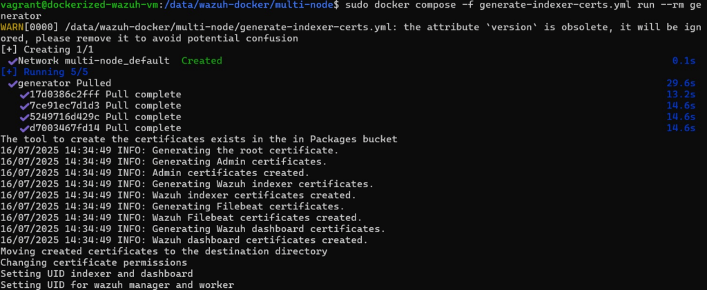
Next, generate the certificates that are needed by Wazuh to work. Make sure to decide to run on a single node or multinode indexer Wazuh. Go to the appropriate directory from the cloned Wazuh git repo. Then run
sudo docker-compose -f generate-indexer-certs.yml run --rm generator
If you are using the newer version aka Version 2 docker compose run the following instead
sudo docker compose -f generate-indexer-certs.yml run --rm generator
Once certificate are generated correctly
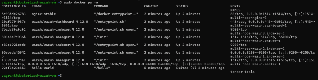
Once the certificate is installed, go to the correct directory then run the following:
sudo docker-compose up -d
Again, should version 2 of docker compose is used run the following instead
sudo docker compose up -d
Wazuh multinode when running correctly
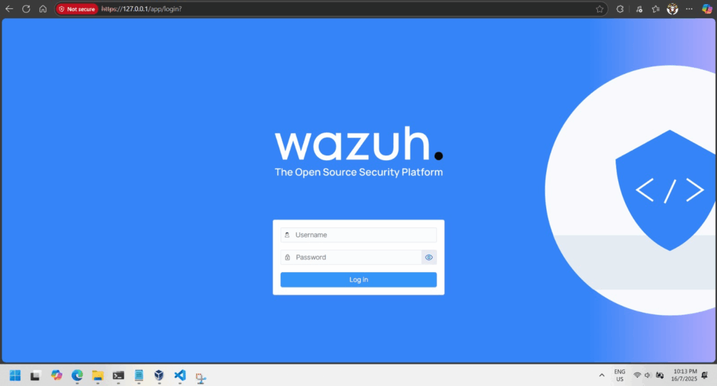
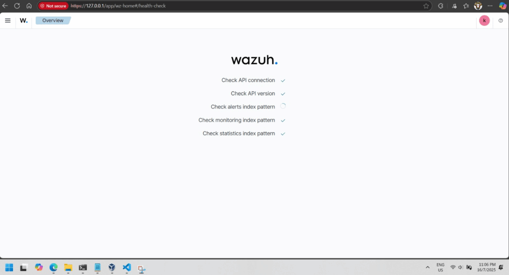
If everything is good you will be able to browse to your Wazuh dashboard in a minute or 2.
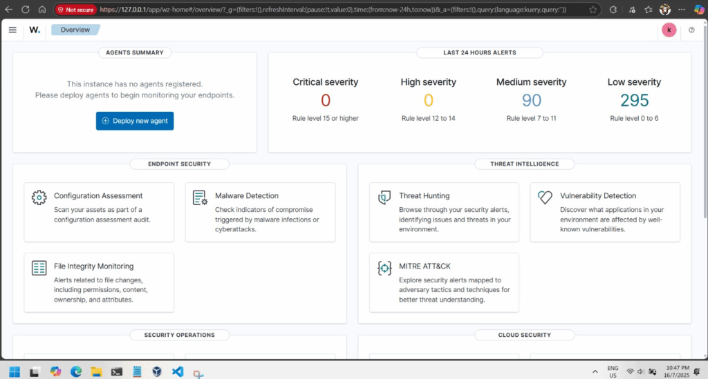
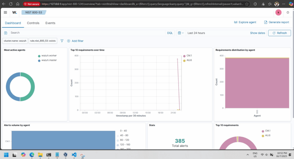
Wazuh dashboard loginFirst time login into Wazuh dashboardWazuh Dashboard overviewSecurity warning or violation visualized
Wazuh SIEM (Security Information and Event Management) platform can help protect systems.
Wazuh SIEM Solution
Wazuh is a free, open-source tool that monitors systems, detects attacks, and logs security events.
It consists of:
Wazuh Server (collects and analyzes logs).
Wazuh Agents (installed on devices to send logs).
Wazuh Dashboard (visualizes threats and alerts).
Simulated Attacks & Findings
Brute Force Attacks: Hackers try guessing passwords repeatedly. Wazuh detects and blocks these attempts.
SQL Injection: Hackers inject malicious code into websites. Wazuh logs and prevents unauthorized access.
Shellshock Attack: Exploits a Linux vulnerability. Wazuh identifies and stops such attempts.
Security Recommendations
Regularly update software to fix vulnerabilities.
Use strong passwords and multi-factor authentication.
Monitor systems with tools like Wazuh to detect threats early.
Conclusion Wazuh helps organizations detect, analyze, and respond to cyber threats before they cause harm. By implementing strong security measures, users can protect their systems from the dangers of the “Wild Web.”
Final Thought: Cybersecurity is essential—tools like Wazuh make it easier to stay safe online!